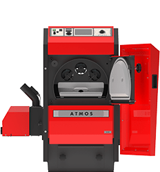
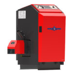
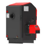
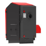
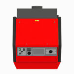
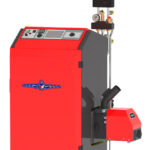
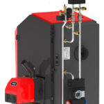
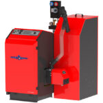
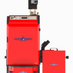
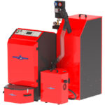
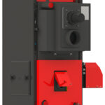
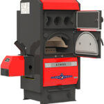
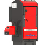
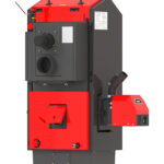
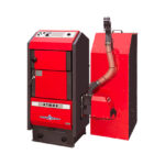
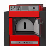
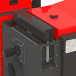
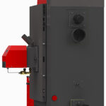
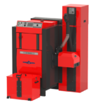
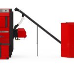
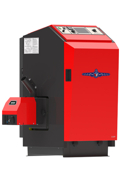
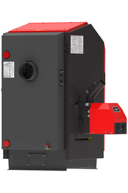
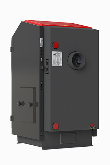
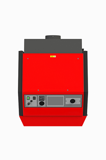
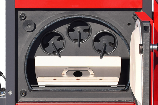
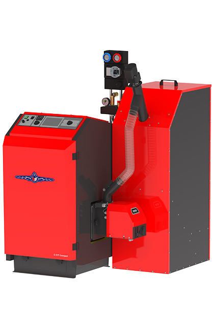
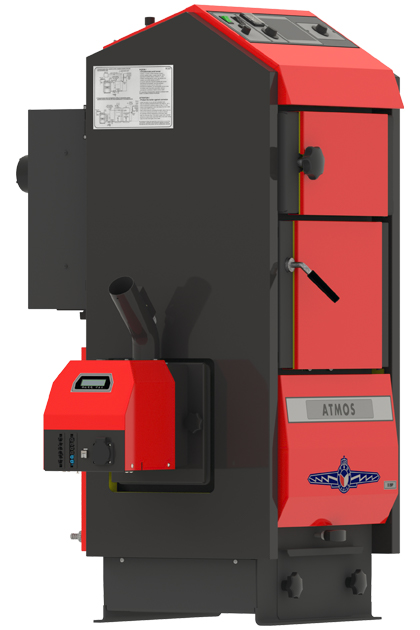
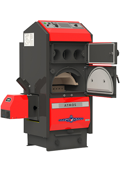
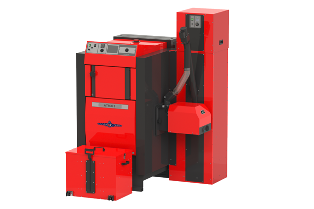
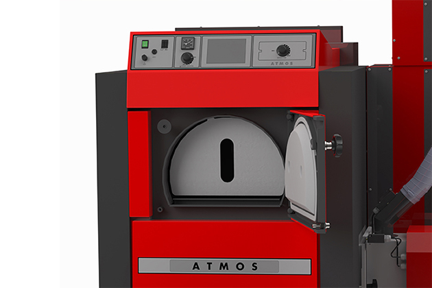
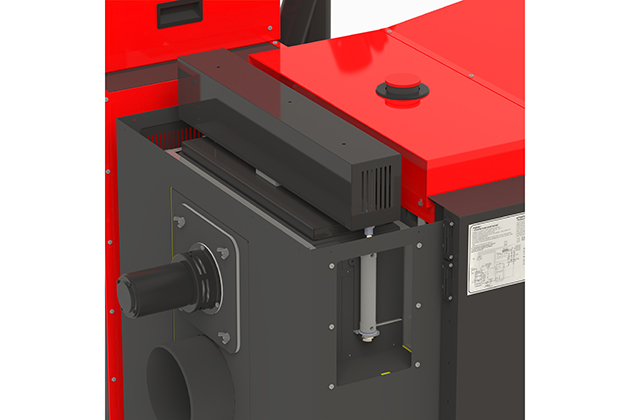
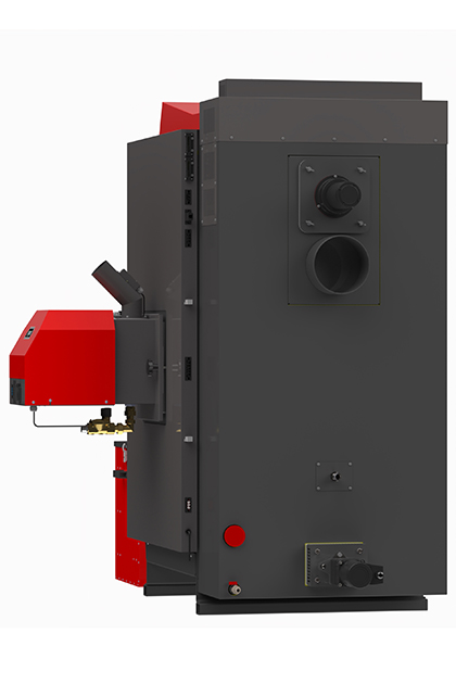
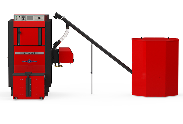
They are designed for perfect combustion of pellets, so that a pellet burner is built into the left or right side of the boiler, according to the customer’s needs, which removes the pellets from the hopper fully automatically using a screw conveyor. The fuel tank is usually located next to the boiler or in an adjoining room and can be of any size (standard 250, 500 or 1000 l). A part of the boiler room is often used as a fuel tank, which is then sufficient for the entire heating season.
The operation of the pellet burner itself works completely automatically. If the burner is instructed to start or there is a need to heat, the conveyor pours the pellets into the burner nozzle and is itself switched on by the heating element (spiral). After sufficient burning of the pellets, the burner starts at the set power, in which it remains until the system (house) is heated. Then the burner is switched off and the pellets in the burner chamber burn out. The burner is thus ready for a new start. The whole cycle is always repeated in case of further needs.
- Boilers D14P, D21P, D25P
- Boilers D14P Compact, D21P Compact, D25P Compact
- Boilers D20P, D30P, D40P, D50P
- Boiler D85P
- The Pellet burners
- Downloads
-
Automatic pellet boilers
-
Boiler efficiency according to type 90,2 - 92,4 %


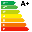
DxxP boilers meets 5th emission class (Energy efficiency class A+), Ekodesign.
Boiler output and other burner functions are controlled by electronic regulation, which allows the boiler operation to be adapted to the specific conditions of the entire system. We refill the pellets, clean the combustion chamber of the burner and remove the ash, once every 1 – 30 days, depending on the quality of the pellets and the size of the hopper. If necessary, the boilers can be equipped with an automatic ash removal system for comfortable heating with minimal maintenance.
Thanks to these features, these boilers are just as comfortable in terms of operation and utility properties as gas heating. The main advantage, however, is that, unlike natural gas, they burn renewable energy sources.
Advantages of ATMOS pellet boilers
- Great heating comfort
- High efficiency 90.2 to 92.4 % depending on type – low fuel consumption
- Ecological combustion – boiler according to EN 303-5:2012 class 5 and EKODESIGN 2015/1189
- Automatic operation and shutdown of the boiler after the fuel burns out
- Automatic ash removal – with built-in ash removal
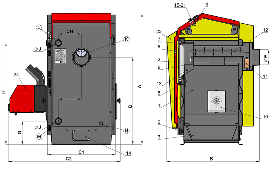
Boilers D14P, D21P, D25P
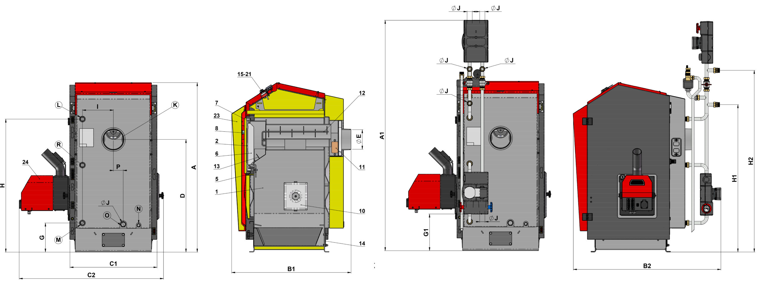
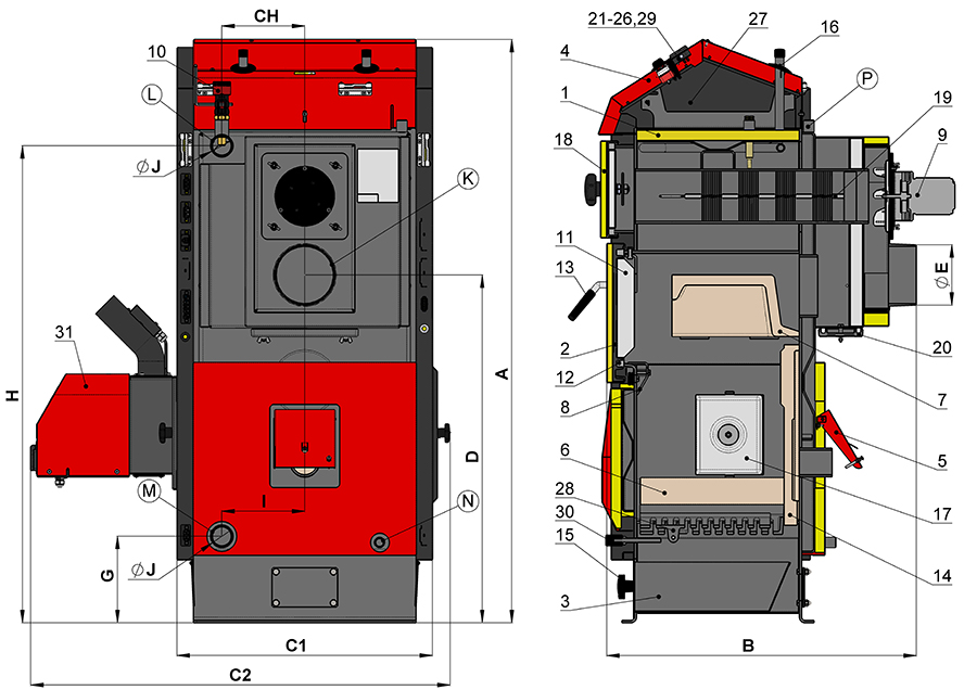
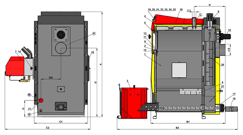
| Description of the boiler drawing D14P, D21P, D25P | |||
| 1. | Boiler body | 16. | Main switch |
| 2. | Cleaning door | 17. | Control (boiler) thermostat |
| 3. | Ashtray | 18. | Pump thermostat |
| 4. | Control panel | 19. | Safety thermostat |
| 5. | Frame shield | 20. | Fuse T6,3A/1500 – H type |
| 6. | Door filling – Sibral | 21. | Double switch for automatic ash removal and pellet burner |
| 7. | Door seal – cord 18 x 18 mm | 23. | Front cover |
| 8. | Closure | 24. | Pellet burner ATMOS A25 |
| 9. | Decorative nut | ||
| 10. | Burner hole cover – plate + insulation | ||
| 11. | Flue cleaning cover | K | – the flue-gas duct neck |
| 12. | Tubesheet air decelerator | L | – water outlet from the boiler |
| 13. | Stainless steel heating screen | M | – water inlet to the boiler |
| 14. | Blanking plug for built-in automatic ash removal | N | – filling valve pipe sleeve |
| 15. | Thermometer | P | – socket for the sensor of the valve controlling the cooling loop (TS 131, STS 20) |
| Boiler dimensions (mm) |
|||
|---|---|---|---|
| D14P | D21P | D25P | |
| A | 1207 | 1207 | 1207 |
| B | 880 | 880 | 950 |
| C1 | 620 | 620 | 620 |
| C2 | 1027 | 1027 | 1027 |
| D | 801 | 801 | 801 |
| E | 150/152 | 150/152 | 150/152 |
| G | 215 | 215 | 215 |
| H | 934 | 934 | 934 |
| CH | 211 | 211 | 211 |
| I | 211 | 211 | 211 |
| J | 6/4″ | 6/4″ | 6/4″ |
| Specification |
Boiler type | ||||
|---|---|---|---|---|---|
| D14P | D21P | D25P | |||
| Rated power | kW | 4 – 14 | 4 – 19 | 7 – 24 | |
| Heating surface | m2 | 1,7 | 1,7 | 2 | |
| Fuel shaft volume | dm3 (l) | 88 | 88 | 88 | |
| Feeding hole dimensions | mm | 270 x 450 | 270 x 450 | 270 x 450 | |
| Prescripted chimney draft | Pa | 16 | 18 | 22 | |
| Max. working overpressure of water | kPa | 250 | 250 | 250 | |
| Boiler weight | kg | 231 | 231 | 254 | |
| Gas-outlet pipe diameter | mm | 150/152 | 150/152 | 150/152 | |
| Ingress protection of electric parts | IP | 20 | 20 | 20 | |
| Electric input – at startup | W | 522 | 522 | 522 | |
| Electric input – during operation | W | 42 | 42 | 42 | |
| Efficiency over the entire performance range | % | 91,9 | 90,7 | 90,7 | |
| Waste gas temperature at nominal output according to EN 303-5 | °C | 127 | 147 | 151 | |
| Flue gas temperature / draft for calculating the flue gas path (chimney) | °C / Pa | 137 / 16 | 157 / 18 | 161 / 22 | |
| Waste gas combustion products flow weight at nominal output | kg/s | 0,011 | 0,015 | 0,018 | |
| Specified fuel (preffered) | high-quality pellets with a diameter of 6 – 8 mm, a length of 10 to 40 mm and a calorific value of 15 – 18 MJ.kg-1 (white pellets) | ||||
| Average fuel (pellets) consumption at nominal output | kg.h-1 | 3,5 | 4,5 | 5,4 | |
| The volume of water in the boiler | l | 56 | 56 | 62 | |
| Boiler hydraulic loss | mbar | 0,18 | 0,18 | 0,19 | |
| Minimum buffer tank volume | l | 500 | 500 | 500 | |
| Connecting voltage | V/Hz | 230/50 | 230/50 | 230/50 | |
| Boiler class | 5 | 5 | 5 | ||
| Energy efficiency class | A+ | A+ | A+ | ||
| Ekodesign | Yes | Yes | Yes | ||

Boilers D14P Compact, D21P Compact, D25P Compact
| Description for D14P Compact, D21P Compact, D25P Compact boiler drawing | |||
| 1. | Boiler body | 17. | Control (boiler) thermostat(code: S0068) |
| 2. | Cleaning door | 18. | Pump thermostat (code: S0023) |
| 3. | Ash pan for D14P, D14P/130, D21P (code: P0097) for D25P – (code: P0080) |
19. | Safety thermostat (code: S0068) |
| 4. | Control panel | 20. | Fuse T6,3A/1500 – typ H |
| 5. | Frame shield | 21. | Double switch of automatic deashing and the pellet burner (code: S0098) |
| 6. | Door filling – Sibral – large (code: S0263) | 22. | Elektroventil pneumatického čištění hořáku |
| 7. | Door seal – cord 18 x 18 mm (code: S0240) | 23. | Front cover (door) (code: S1252) |
| 8. | Closure (code: S1047) | 24. | ATMOS A25 pellet burner |
| 9. | Decorative nut (code: S0413) | ||
| 10. | Lid of the burner opening – plate + insulation (code: S0275) | ||
| 11. | Cleaning lid of the smoke channel | K | – flue gas orifice (150/152 mm) |
| 12. | Tube plate decelerator | L | – water outlet from the boiler (1”) |
| 13. | Stainless-steel screen of the combustion chamber for D14P, D14P/130, (P14) (code: S0936) for D21P, D25P (P21, P25) (code: S0937) |
M | – water inlet to the boiler (1”) |
| 14. | Blind flange for installation of automatic deashing | N | – socket for the filling tap (1/2”) |
| 15. | Thermometer | O | – expansion tank sleeve (1”) |
| 16. | Main switch (code: S0091) | R | – water outlet from boiler for boiler circuit (1”) |
| Boiler dimensions (mm) | ||||
| D14P | D14P /130 | D21P | D25P | |
| A / A1 | 1207 / 1635 | 1207 / 1635 | 1207 / 1635 | 1207 / 1635 |
| B1 | 850 | 850 | 850 | 950 |
| B2 / B3 | 1095 / 1300 | 1095 / 1300 | 1095 / 1300 | 1195 / 1300 |
| C1 / C2 | 620 / 1027 | 620 / 1027 | 620 / 1027 | 620 / 1027 |
| E | 150/152 | 130 | 150/152 | 150/152 |
| G / G1 | 207 / 266 | 207 / 266 | 207 / 266 | 207 / 266 |
| H | 947 | 947 | 947 | 947 |
| CH | 220 | 220 | 220 | 220 |
| I | 220 | 220 | 220 | 220 |
| J | 1” | 1” | 1” | 1” |
| P | 70 | 70 | 70 | 70 |
| Q | 1” | 1” | 1” | 1” |
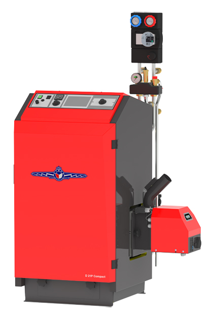
- D 21 P Compact – front view
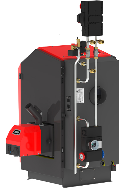
- D 21 P Compact – rear view
- D 21P Compact with AZPD 300

Boilers D20P, D30P, D40P, D50P
| Description of the boiler drawing D20p, D30P, D40P, D50P | |||
| 1. | Boiler body | 19. | Air decelerator(type D20P – 3x brush, D30P, D40P a D50P – 1x brush + 2x steel) |
| 2. | Filling door | 20. | Cleaning lid of the rear drain |
| 3. | Ashtray | 21. | Thermometer |
| 4. | Control panel | 22. | Main switch |
| 5. | Regulating air damper – only for wood heating | 23. | Control (boiler) thermostat |
| 6. | Heat-resistant fitting – bottom of the combustion chamber | 24. | Pump thermostat |
| 7. | Heat-resistant fitting – upper spherical space | 25. | Safety thermostat |
| 8. | Frame screen | 26. | Fuse T6,3A/1500 – H type |
| 9. | Exhaust fan | 27. | Condenser for exhaust fan – 1μF |
| 10. | Draught regulator – HONEYWELL FR124 | 28. | Grate |
| 11. | Door filling – Sibral | 29. | Double switch for automatic ash removal and pellet burner |
| 12. | Door seal – cord 18 x 18 mm | 30. | Grate pipe |
| 13. | Closure – handle | 31. | Pellet burner |
| 14. | Heat-resistant fitting – rear part of spherical space | K | – the flue-gas duct neck |
| 15. | Ashtray cap – nut | L | – water outlet from the boiler |
| 16. | Cooling loop against overheating | M | – water inlet to the boiler |
| 17. | Burner hole cover | N | – filling valve pipe sleeve |
| 18. | Tube cover cleaning lid | P | – socket for the sensor of the valve controlling the cooling loop (TS 131, STS 20) |
| Boiler dimensions (mm) |
||||
| D20P | D30P | D40P | D50P | |
|---|---|---|---|---|
| A | 1405 | 1405 | 1405 | 1405 |
| B | 652 | 954 | 954 | 1052 |
| C | 606 | 606 | 606 | 606 |
| D | 848 | 848 | 848 | 848 |
| E | 150/152 | 150/152 | 150/152 | 150/152 |
| G | 211 | 211 | 211 | 211 |
| H | 1163 | 1163 | 1163 | 1163 |
| CH | 202 | 202 | 202 | 202 |
| I | – | – | – | – |
| J | 6/4″ | 6/4″ | 6/4″ | 6/4″ |
| Specification | Boiler type | ||||
|---|---|---|---|---|---|
| D20P | D30P | D40P | D50P | ||
| Rated power | kW | 6,5 – 22 | 8,9 – 29,8 | 8,9 – 40 | 13,5 – 45 |
| Heating surface | m2 | 2 | 2,7 | 2,7 | 3,6 |
| Fuel shaft volume (reservoir) | dm3 (l) | 70 | 105 | 105 | 140 |
| Feeding hole dimensions | mm | 270 x 450 | 270 x 450 | 270 x 450 | 270 x 450 |
| Prescripted chimney draft | Pa | 15 | 21 | 22 | 23 |
| Max. working overpressure of water | kPa | 250 | 250 | 250 | 250 |
| Boiler weight | kg | 305 | 370 | 386 | 430 |
| Gas-outlet pipe diameter | mm | 150/152 | 150/152 | 150/152 | 150/152 |
| Ingress protection of electric parts | IP | 20 | 20 | 20 | 20 |
| Electric input – at startup | W | 572 | 530 | 530 | 530 |
| Electric input – during operation | W | 92 | 97 | 97 | 97 |
| Efficiency over the entire performance range | % | 91,1 | 92,4 | 91,0 | 91,1 |
| Boiler class | 5 | 5 | 5 | 5 | |
| Energy efficiency class | A+ | A+ | A+ | A+ | |
| Flue gas temperature at rated power | °C | 128 | 158 | 157 | 123 |
| Waste gas combustion products flow weight at nominal output | kg/s | 0,016 | 0,025 | 0,031 | 0,035 |
| Specified fuel (preffered) | quality pellets with a diameter of 6 – 8 mm with a calorific value of 16 – 19 MJ.kg-1 | ||||
| Average fuel (pellets) consumption at nominal output | kg.h-1 | 5 | 6,8 | 9,4 | 10,6 |
| The volume of water in the boiler | l | 82 | 91 | 91 | 117 |
| Boiler hydraulic loss | mbar | 0,22 | 0,23 | 0,23 | 0,24 |
| Minimum buffer tank volume | l | 500 | 750 | 750 | 1000 |
| Connecting voltage | V/Hz | 230/50 | 230/50 | 230/50 | 230/50 |
| Ekodesign | |||||
- D20P – side view with burner
- D20P – rear view

Boiler D85P
ATMOS D85P hot water boilers are designed for comfortable heating of residential houses, various establishments and other similar objects with pellets. High-quality wood pellets with a diameter of 6 to 8 mm can be used for heating. The boiler is not designed for burning wood, sawdust and small wood waste.
The boilers are designed so that an ATMOS A85 pellet burner with pneumatic cleaning of the combustion chamber of the burner and the tube heat exchanger is built into their left or right side. The boiler body is made as a weldment from steel sheets with a thickness of 3 – 6 mm. They consist of a combustion chamber with a large vault and in the lower part of the chamber there is a slit to the channel with a screw conveyor discharging the ash to a large external tank (160 l) of automatic ash removal. The front wall of the boiler is equipped with a cleaning door in the upper part, behind which a stainless steel screen with a window is inserted, ensuring the protection of the door against overheating. In the rear part of the boiler there is a tube heat exchanger equipped with segment brakes with the function of automatic cleaning without the need to remove them. The boiler body is thermally insulated from the outside with mineral wool inserted under the sheet metal covers of the outer casing of the boilers. In the upper part of the boilers there is a panel with a main switch, automatic ash removal switch, pellet burner switch (L2), operating (regulating) thermostat, pump thermostat, safety thermostat, thermometer and 6.3 A fuse. The boiler is not equipped with a cooling loop against overheating. , because due to the small amount of fuel in the burner there is no danger of overheating the boiler in the event of a power failure. energy. The D85P boiler is equipped with an exhaust fan with a speed sensor.
| Description of the boiler drawing D85P | |||
| 1. | Boiler body | 18. | Exhaust fan condenser – 2 μF |
| 2. | Filling door | 19. | Thermometer |
| 3. | Ashtray | 20. | Main switch |
| 4. | Control panel | 21. | Control (boiler) thermostat |
| 5. | Door screen | 22. | Pump thermostat |
| 6. | Combustion chamber shield | 23. | Safety thermostat |
| 7. | Burner ATMOS A85 | 24. | Fuse T6,3A/1500 – H type |
| 8. | Pneumatic tubesheet cleaning | 25. | Double switch for automatic ash removal and pellet burner |
| 9. | Frame screen | 26. | Air decelerator for tubesheet |
| 10. | Fan with speed sensor – exhaust | 27. | Air inlet for pneumatic cleaning of the tubesheet |
| 11. | Door filling – Sibral | 28. | Valve for pneumatic burner cleaning |
| 12. | Door seal 18 x 18 mm | ||
| 13. | Closure – handle | ||
| 14. | Decorative nut | K | – flue gas neck |
| 15. | Burner hole cover – plate + insulation | L | – water outlet from the boiler |
| 16. | Engine with gearbox for ash removal | M | – water inlet to the boiler |
| 17. | Automatic ash removal screw | N | – socket for the filling tap |
| Boiler dimensions (mm) | D85P |
| A | 1840 |
| B1 | 1303 |
| B2 | 2113 |
| C1 | 1014 |
| C2 | 1589 |
| D | 1204 |
| E | 200 |
| G | 288 |
| H | 545 |
| CH | 350 |
| I | 2” |
| Specification | ||
| D85P | ||
| Rated power | kW | 24 – 80 |
| Heating surface | m2 | 6,5 |
| Fuel shaft volume | dm3 (l) | 492 |
| Feeding hole dimensions | mm | 260 x 450 |
| Prescripted chimney draft | Pa/mbar | 22/0,22 |
| Max. working overpressure of water | kPa/bar | 250/2,5 |
| Boiler weight | kg | 774 |
| Gas-outlet pipe diameter | mm | 200 |
| Ingress protection of the electric part | IP | 20 |
| Electric input – at startup – during operation |
W | 635 (1135) 134 |
| Efficiency over the entire performance range | % | 91,6 |
| Boiler class | 5 | |
| Energy efficiency class | A+ | |
| Flue gas temperature at rated power | °C | 149,2 |
| Waste gas combustion products flow weight at nominal output | kg/s | 0,062 |
| Specified fuel (preffered) | quality pellets with a diameter of 6 – 8 mm with a calorific value of 16 – 19 MJ.kg-1 | |
| Average fuel (pellets) consumption at nominal output | kg.h-1 | 18,8 |
| The volume of water in the boiler | l | 230 |
| Boiler hydraulic loss | mbar | 0,24 |
| Minimum buffer tank volume | l | 1000 |
| Connecting voltage | V/Hz | 230/50 |
| The prescribed minimum return water temperature in operation is 65 °C. The prescribed operating temperature of the boiler is 80 – 90 °C. | ||
- D85P
- D85P – door screen
- detail of pneumatic tube sheet cleaning
- rear view of the boiler D85P
- One of the options for connecting a boiler with a pellet tank

The Pellet burners
Pellet burner ATMOS A25 for boilers D10PX, D15PX, D20PX and D25PX
Specified fuel: good quality pellets with 6 – 8 mm diameter, 5 – 25 mm lenght and 16 – 19 MJ.kg-1 caloric power (white pellets).
The burner screen: used to display the current status of the burner and adjusting its functions.
Burner control: with an AC07X electronic control unit that controls the operation of the external conveyor, two ignition spirals and the fan in accordance with requirements of the boiler and the heating system. The electronic system is rotected with the safety thermostat of the boiler, safety thermostat at the pellet supply to the burner, the fan speed transducer and the flame sensing photocell. The operation of the burner is indicated on the electronic control display.
Burner in version for boilers DxxPX contains moreover additional module AC07X-C – (R5, R6) to controle pneumatic cleaning system for pellet burner or other possible aplications.
Ignition of fuel: automatic assisted by two electric ignition spirals (one ignition spiral 522W).
Basic functions of burner:
Spare outputs R and R2 for control of exhaust fan of the boiler and pump in the boiler circuit (connected from the production)
The possibility of using two spare outputs R5 and R6 for various applications
The possibility of the involvement of four different sensors TS, TV, TK and TSV
TK – boiler temperature sensor (connected from the production)
TSV – flue gas temperature sensor (connected from the production)
TS – temperature sensor on the tank bottom
TV – temperature sensor on the tank top
- control of boiler fan from burner with the help of the spare output (R- reserve) (connected from the production) (except D10PX)
- control of boiler pump from burner with the help of the spare output (R2- reserve) (connected from the production)
- burner controlling it in accordance with two temperatures (sensors) on the buffer (accumulation) tank
Fuel feeding: for boilers DxxPX is designed special auger conveyor DRA25 which is inbuilded directly inf the boiler. This conveyor is controlled from electronic regulation of burner and dose the fuel from the reservoir in to the burner.
Pellet burner ATMOS A45 for boilers D30P, D40P, D50
Prescribed fuel: quality wood pellets (white) with a diameter of 6 to 8 mm, a length of 5 to 25 mm and a calorific value of 16 – 19 MJ.kg-1.
Burner display: used to display the current status of the burner and to set its functions
Burner control: electronic control AC07X, which controls the operation of the external conveyor, two ignition coils and the fan according to the requirements of the boiler and the heating system. The electronics are protected by a boiler safety thermostat, a safety thermostat on the pellet supply to the burner, a fan speed sensor and a photocell for flame sensing. The burner operation is signaled on the electronic control display.
Fuel ignition: automatic by means of two electric ignition coils.
Basic burner functions:
Reserve outputs R and R2 for controlling the boiler exhaust fan and the pump in the boiler circuit (connected from the factory)
Possibility of connecting four different sensors TS, TV, TK and TSV
TK – boiler temperature sensor (connected from production)
TSV – flue gas temperature sensor (connected from production)
TS – low temperature sensor on the tank
TV – top temperature sensor on the tank
- control of the boiler fan from the burner by means of a reserve output (R) (connected from the factory)
- control of the boiler pump from the burner by means of a reserve output (R2) (connected from the factory)
- burner control according to two temperatures on the expansion tank
Fuel dosing: special DRA type screw conveyors are designed for DxxP boilers.
Pellet burner ATMOS A85
The A85 burner is basically equipped with a pneumatic cleaning system, which cleans the combustion chamber of the burner every time it burns out or at regular intervals. Thanks to pneumatic cleaning, it is sufficient to check or clean the combustion chamber of the burner once every 14 days to a month.
We always connect the D80P boiler with the A85 burner with a buffer tank with a minimum volume of 1000 l, where we use the function of controlling the burner according to two temperatures on the buffer tank and controlling the boiler exhaust fan directly from the burner.
The following conveyors are designed for these burners:
Shaft screw conveyor for burner ATMOS A45 / 85 – DRA50 with a length of 1.7 m and a diameter of 80 mm
Shaft screw conveyor for burner ATMOS A45 / 85 – DRA50 with a length of 2.5 m and a diameter of 80 mm
Shaft screw conveyor for burner ATMOS A45 / 85 – DRA50 with a length of 4 m – straight and a diameter of 80 mm
Shaft screw conveyor for burner ATMOS A45 / 85 – DRA50 with a length of 5 m – straight and a diameter of 80 mm


